New Product

Ozone (Ambient) / Chemical & Petrochemical / Pharma / Water & Waste Water
Model 205 Dual Beam Ozone Monitor High

Ozone (Industrial) / Chemical & Petrochemical / Pharma / Water & Waste Water
106-MH Ozone MonitorTM (Industrial)


Ozone (Industrial) / Automotive & Manufacturing / Chemical & Petrochemical / Dairy / Food & Beverage / Lab & Gas / Pharma / Plastics / Power & Steam
106-HIndustrial Ozone MonitorTM


Test & Measurement
Instruments
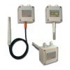
H5 Electronic Humidity

Features
- Wall, duct mount or remote sensor relative humidity electronic transmitter
- With replaceable “Humy-chip” capacitive sensor and filters
- Voltage, Current or PT100 output according to the selected signal and model
- Alarm digital output
- Reading, calculation and display of several variables:
- Relative humidity (RH)
- Temperature (T)
- Dew Point (DP)
- Temperature difference between T and DP (ΔT)
- Data and event logging
- RS 485 port with ModBus RTU protocol (optional)
- LCD Display (optional)
Specifications & Spare Parts
| Process Inputs | |
| “Humy Chip” for temperature and Humidity acquisition Self Calibrating |
|
| 2 Reciprocally Insulated Outputs | |
| Available Output Signals: | |
| – Voltage (V): 0…10 V, 0…1V (Min. impedance 500Ω) – Current (mA): 0/4…20 mA (Max. impedance 500Ω) – 3 wire PT100 accuracy class B (1/2 DIN) Any of the two outputs may be configured for Humidity, Temperature, ΔT, and Dew Point. |
|
| Selectable Outputs | |
| Humidity | Accuracy: 1.8% between 10… 90% RH Range: 0… 100% RH Long-term drift: typically <0.5% RH/year |
| Temperature | Accuracy: <0.5°C between 0… +50°C (32… 122°F) Available Ranges: -30.0… +70.0°C (-22… 158°F) -20.0… +30.0°C (-4… 86°F) 0.0… +50.0°C (32… 122°F) 0.0… +100.0°C (32… 212°F) |
| Dew Point (DP) | Accuracy: <1°C between 30… 100% RH and -20… +90°C (-4… +164°F) Available Ranges: -30.0… +70.0°C (-22… 158°F) 0.0… +100.0°C (32… 212°F) Other ranges available on request in °C or °F |
| ΔT (between T and DP) | Available Range: 0.0… 50.0°C (32… 122°F) |
| Digital Output for Alarm | 1 Relay SPST-NO 1A (30 V) |
| Power Supply | – With (mA) Output: 10… 30 Vdc – With (V) Output: 18… 27 Vac or 20… 30 Vdc |
| Functions | |
| – Humidity and temperature retransmission – Dew point calculation – ΔT calculation (as difference between actual temperature and dew point) – Up to 5 alarms freely configurable to the relay output – Data and event logging |
|
| Communication and Programming | |
| Interfaces | RS 485 port with ModBus RTU and J-bus (slave) protocols (optional) |
| Programming/Configuration Tools | Configuration software available for PC |
| Installation | |
| Mounting Method | Wall mount, Duct mount, Remote sensor |
| Case Dimensions | 100 x 100 x 61 mm |
| Cable Gland | 35 mm max. |
| Cable Probe Connector | 25 mm |
| Protection Filter | – Wire mesh – Sintered stainless steel – Teflon Protects against dust and other atmospheric contaminants. |
| Display and Indicators | |
| LCD Display (Optional) | Size: 3.65 mm, 3 digits, 16 characters |
| Connectable to | |
| – Any controller from Ascon Tecnologic range with the appropriate I/Os – SCADA for monitoring, traceability, and remote management – DX and DY gateways for remote monitoring |
|